Products
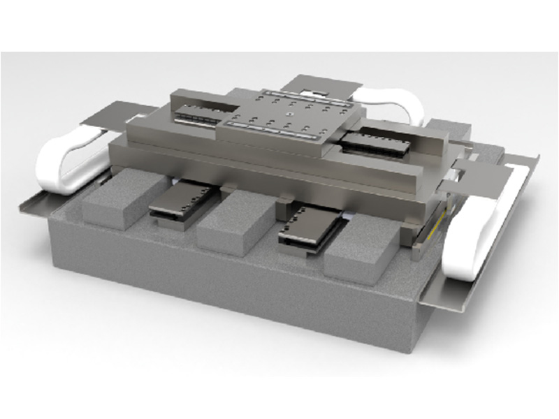
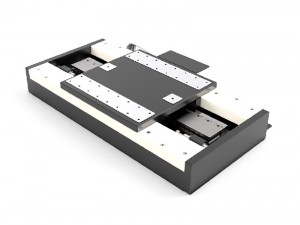
E-ABT-XY-360X360 (Ceramic linear motor stage) XY Air bearing Linear Motor Stage
● Ideal for scanning applications or high-precision positioning
● Cleanroom compatible
● Travel ranges to 360 mm × 360 mm
● Load capacity to 500 N
● Resolution to 4.88nm or 1 nm, Velocity to 500mm/s
● Incremental encoder or Absolute encoder
● Alumina ceramic versions are available, a material that offers the highest precision and performance, but at a higher price.
Accessories and options
● Filter and Air Preparation Kits
● Additional axes
● Machine bases
● Base plates made of granite and systems for reducing vibration
● Suitable mounts for additional positioners such as tip/tilt platforms or 6-axis positioners with piezo drives.
Application fields
Positioning systems are ideally suited for many high-precision applications, such as metrology, photonics, and precision scanning as well as in semiconductor or flat panel display manufacturing.
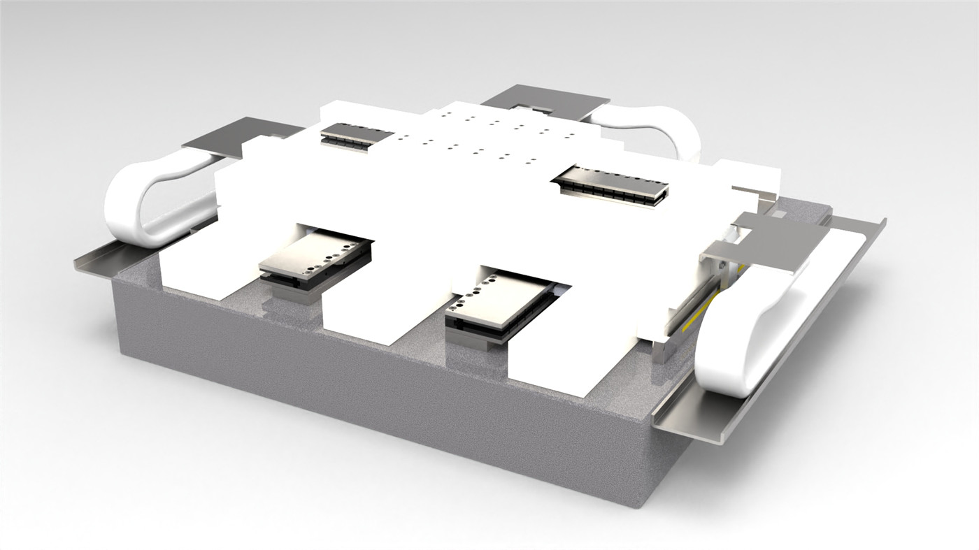
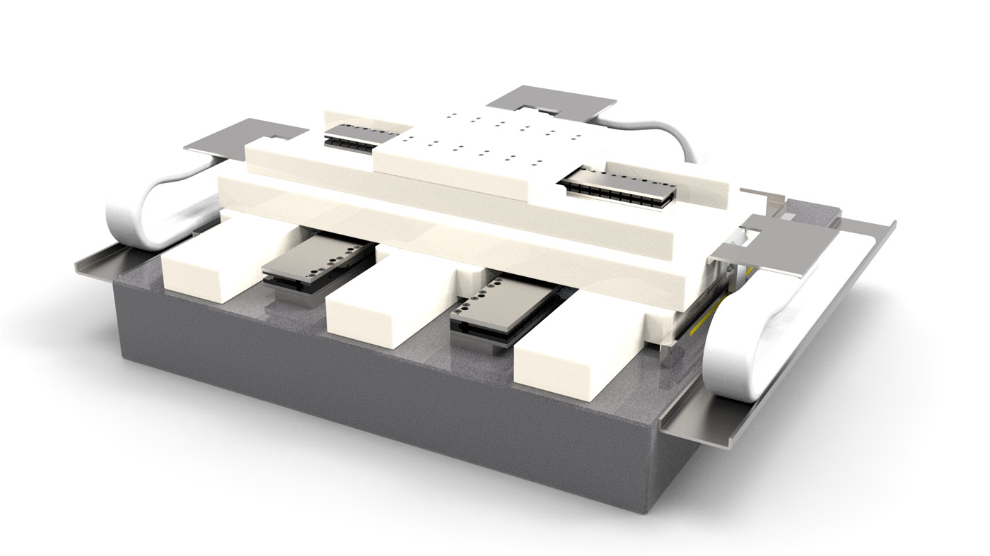
Long lifetime, cleanroom compatible drag chains
The E-ABT-XY-360X360 has high-quality, long-lasting ribbon cables and pneumatic hoses. Extensive research and development has resulted in an optimized cable management system that enables millions of maintenance-free cycles. Teflon coating ensures low particle formation
Thanks to the friction-free motion, no particles are formed, which makes PIglide stages ideal for cleanroom applications.
| Specification | Commomn material | Ceramic material |
| Motor type | Three-phase iron core motor | |
| Opticval Encode resolution | sincos 4.88nm(other higher resolutions are optional) | |
| X axes Motor thrust[N] | Continuous 90N peak 315N | |
| Y axes Motor thrust[N] | Continuous 219N*2 Peak 750N*2 | |
| X axes No-load acceleration[g] | 4.5G | |
| Y axes No-load acceleration[g] | 3G | |
| Min step size[nm] | 10nm(with nanopwm or linear driver) | |
| Travel [mm] | 360×360 | |
| Repeatability Accuracy [um] | ±0.15 | ±0.1 |
| Accuracy [um] | ±0.5 | ±0.3 |
| Flatness [um] | ±1 | ±0.5 |
| Straightness [um] | 1.5 | 1 |
| Max Speed [mm/s] | 500mm/s | |
| Max Load [kg] | 50kg | |
1) What is “Nanopositioning”?
A: In the not-too-distant past, the precision tail-end of the bell curve in automation was often colloquially referred to as the “micropositioning” segment of the market. The term microposition derives from the fact that high-precision positioning systems were routinely operating at the micron level. Manufacturers in this space were specifying key system attributes such as Bi-directional repeatability, Accuracy, and Stability in units of microns. Such systems sufficiently filled industry demands from Life Science and Diagnostics, to Non-contact metrology, to the Tech sectors of Semiconductor, Data Storage, and Flat Panel Display.
Fast forward to our present day and no longer are such systems sufficient. Evolving industry needs in microscopy and biotechnology demand evolving levels of performance from precision positioning equipment manufacturers. As the features of interest across markets become smaller, the ability to position at the nanometer level becomes a market imperative.
2) Does your product ship overseas?
A: Yes, we ship our products internationally and have distributors in designated areas.
3) How do I ask for a quote on a specific product?
A:You can send a email to us , we will make a official quotation to you.
4) Are the products customizable?
A: We provide the ultimate engineered motion solutions for our clients. In many cases this involves customizing or configuring our standard products to a client’s unique application and specifications. Please contact us if you’re interested in customizing or configuring one of our standard products, or if you’d like to work with our engineering team to design a unique solution to meet your needs of the feedback source. If this velocity is exceeded, the commutation initialization is no longer valid, and commutation must be reinitizlized.
5)What is gantry stages?
A: The gantry stages are designed to provide unsurpassed repeatability and excellent throughput under real world operating conditions. Our gantry stages are designed to move such items as inspection cameras, laser heads, or specific customer tooling over either removable substrates or fixtures mounted to the base of the system. The gantry base can be provided with mounting holes for interfacing a customer’s hardware to the stage. Due to its simplicity and ease of assembly, it is the ideal gantry stage configuration for OEMS and system integrators building machines for demanding applications. Many of Dover Motion’s standard screw driven and servo motor linear products can be integrated together as a gantry stage to achieve an application’s required accuracy and travel for XYZ motion.
●Pre-formatted base for ease of integration;
●Risers to provide space between the base and moving beam;
●Integrated cable tracks and hi flex cable;
●All axes tested together and burned in to ensure performance and reliability requirements are met before shipment.

